Alternative Tuning Methods
9.1 SVID OFFSET UNDERVOLT
PDF · 22Page 22For LGA1700 / ASUS Z790, tune a negative SVID offset with LLC, AC/DC and SVID Behavior held constant. Manual AC is compatible with subsequent offset tuning, but an existing AC undervolt does not guarantee additional margin. Evaluate AC, offset and the VRM load-line together as a single configuration.
| BIOS setting | Starting setting | Purpose / limitation |
|---|---|---|
| Global Core SVID Voltage | Adaptive Mode | Adjusts the CPU request, not the manual VRM output |
| Offset Mode Sign / Offset Voltage | "-" sign; magnitude set separately | Start with no offset specified; 0.010 V = 10 mV |
| Actual VRM Core Voltage / Cache SVID Voltage | Auto / Auto | Do not add a manual VRM setting or a separate Ring offset |
| Additional Turbo Mode CPU Core Voltage | Auto | Do not specify a separate turbo voltage |
| CPU Load-line Calibration | Choose and hold constant | A validated level, not necessarily LLC6 |
| SVID Behavior | Chosen baseline | Auto or another previously validated Behavior |
| IA AC Load Line | Auto or manual AC | Choose before tuning offset; do not lower both together |
| IA DC Load Line | Match to LLC: Table 3.2 | Not automatically equal to AC; not an undervolting control. Verification - 5.2 |
| Limits / CEP / UVP | As in the main method | Finite PL/ICCMAX; protections enabled (4.2) |
Tuning sequence: baseline first, then offset
- Save the profile and record the BIOS/microcode, clocks, memory and results. Before tuning offset, hold LLC, SVID Behavior and AC/DC constant. For independent manual AC/DC, set Synch ACDC to Disabled; verify the applied values after boot.
- Validate the baseline without a global offset, using finite limits and protections. For a manual AC undervolt, use a previously validated setting with margin, not AC at its stability limit. If errors or performance loss occur, do not add a negative offset.
- Change only the offset in steps such as 5-10 mV, saving BIOS settings and rebooting. Do not lower AC at the same time. Compare VID, VOUT, performance and Effective Clocks under comparable conditions. If results worsen, undo the step and retain margin.
- Repeat 5.3-5.4: heavy load, P/E-cores and peak boost, idle, transitions, sleep/wake and real workloads. After changing LLC, AC/DC, Behavior, Synch or the BIOS/profile, validate the baseline and offset again.
Global does not promise the same shift for P/E/cache: a shared power rail does not mean identical requests or V/F relationships. CEP may limit performance; do not disable UVP as a routine step for BIOS undervolting. LGA1851 is covered separately (8.1).
A benefit is confirmed by maintaining performance with lower energy use, or increasing performance with comparable energy use and cooling. Lower VID, temperature or Package Power readings alone are not enough.
9.2 FIXED: Manual Voltage
PDF · 23Page 23My starting point: LGA1700, 14900KS, ASUS ROG Maximus Z790 Apex Encore / BIOS 2202; LLC6, P/E/Ring 5800/4500/5000, 1.35 V, HT Off. The remaining fields form a validation plan, not an export; the clocks and HT setting are specific to this example, not requirements for FIXED.
FIXED sets a manual VRM voltage target; clocks are controlled separately. In steady state: VOUT ≈ VOverride - IOUT × RLL (RLL is the load-line slope). A 1.350 V target does not equal VOUT under every load: current, LLC and transient overshoot must be considered separately.
F7: E = Extreme Tweaker; D = E > Digi+ VRM; I = E > Internal CPU Power Management; T = E > Tweaker's Paradise. C = Advanced > CPU Configuration; A = C > CPU - Power Management Control. Tau = Package Power Time Window.
| BIOS setting / path | LLC6: main branch | LLC5: separate trial |
|---|---|---|
| D: CPU Load-line Calibration | Level 6 | Level 5 |
| I: IA AC Load Line / IA DC Load Line | 0.49 / 0.49 mΩ | 0.73 / 0.73 mΩ |
| D: Synch ACDC Loadline with VRM Loadline | Disabled | Disabled |
| E: Actual VRM Core Voltage > CPU Core Voltage Override | Manual Mode / 1.350 V | Manual Mode / 1.350 V |
| E: SVID Behavior / I: CPU SVID Support | Auto / Enabled | Auto / Enabled |
| E: Global Core SVID Voltage / Cache SVID Voltage | Auto / Auto | Auto / Auto |
| E: Performance / Efficient Core Ratio; ALL-Core Ratio Limit | Sync All Cores; 58 / 45 | Sync All Cores; 58 / 45 |
| E: Min./Max. CPU Cache Ratio; Ring Down Bin | Auto / 50; Enabled | Auto / 50; Enabled |
| E: ASUS MultiCore Enhancement | Disabled - Enforce All limits | Disabled - Enforce All limits |
| I: Long / Short Duration Package Power Limit; Tau | 253 / 253 W; 56 s | 253 / 253 W; 56 s |
| I: CPU Core/Cache Current Limit Max.; Unlimited ICCMAX | 307 A; Disabled | 307 A; Disabled |
| I: IA CEP / SA CEP; T: UnderVolt Protection | Enabled (all) | Enabled (all) |
| I: Maximum CPU Core Temperature; D: CPU Current Reporting | 90 °C; 100% | 90 °C; 100% |
| D: CPU Voltage Suspension; C: Hyper-Threading | Disabled (both) | Disabled (both) |
| A: CPU C-states / Thermal Monitor | Enabled / Enabled | Enabled / Enabled |
Choose DC for the selected LLC from Table 3.2. AC = DC is the reference baseline for this trial, not a requirement for FIXED mode. 253 W / 307 A / 90 °C are the trial limits; Ring 50 is the ceiling. For comparison with SVID offset, keep clocks, HT, memory, limits and cooling identical.
Sequence: LLC6 first, then a separate LLC5 branch
- Save the profile; use BCLK 100 MHz and keep memory settings unchanged. ABT and Overclocking TVB = Disabled; V/F, per-core offsets, CPU Core/Cache Boot Voltage = Auto. Enter the LLC6 column settings, press F10 and reboot; verify AC/DC, ratios, HT and limits.
- Use a short load to check VOUT/IOUT and temperature. Before lowering Override, validate the starting 1.350 V setting using 5.3-5.4. If errors or unexplained performance loss occur, review the baseline first instead of continuing to lower it.
- Lower only Override in 0.005 V steps; check VOUT/IOUT, temperature, Effective Clocks and the result of the same test. If performance drops, check for limits; the absence of errors does not mean success. If results worsen, undo the step and retain margin.
- For LLC5, restore the starting Override of 1.350 V and change LLC/AC/DC as shown in the table. At the same Override and current, LLC5 produces more Vdroop than LLC6; compare VOUT using measurements. This is a separate trial. If it fails, return to LLC6 or lower clocks; do not automatically raise voltage.
- Revalidate each branch using 5.3-5.4, including warm-up, load/idle and sleep/wake. Power/current/temperature limits may lower clocks: such a run does not validate stability at 58/45/50.
9.2.1 FIXED: Benchmark Tuning
PDF · 24Page 24LGA1700 / ASUS Z790. Supplement to 9.2: the goal is the highest possible result in the selected benchmark, not a universal daily-use profile. A successful run does not prove system stability under other loads. E/D/I/C/A paths are as defined in 9.2.
| BIOS settings | What to change or check against the 9.2 baseline |
|---|---|
| E: Performance / Efficient Core Ratio; Min./Max. CPU Cache Ratio | Tune P/E and Ring for the test and cooling. Choose Sync All Cores or By Core Usage according to the load; ABT and Overclocking TVB = Disabled. Setpoints do not guarantee sustained clocks: account for Ring Down Bin, Core / Effective Clocks and the actual Ring clock. |
| I: Long / Short Duration Package Power Limit; Package Power Time Window | Raise PL1/PL2 when they are the limiting factor; Auto may be retained if the actual limits do not constrain the test. MCE = Enabled - Remove All limits is a separate option, not a synonym for Auto. Tau controls power averaging; with PL1 = PL2 there is no transition to a lower limit. |
| I: CPU Core/Cache Current Limit Max.; Unlimited ICCMAX | Raise ICCMAX when current is the limiting factor. For an extended range: Unlimited ICCMAX = Enabled; check the applied ICCMAX and Limit Reasons. This does not disable all protections or replace the separate VRM CPU Current Capability limit. |
| E: Actual VRM Core Voltage > CPU Core Voltage Override; D: CPU Load-line Calibration | Tune Override for performance, not minimum Vcore. Here: LLC6 / DC 0.49 mΩ or LLC7 / DC 0.24 mΩ (3.2). Compare VOUT, droop and heat; LLC7 increases compensation and the risk of overshoot. Maximum LLC is not needed by default. |
| C: Hyper-Threading / Active Efficient Cores; A: CPU C-states / SpeedStep / Speed Shift | HT = Enabled (ON) is the baseline: Cinebench Multi Core results are usually higher. Active Efficient Cores = All is the starting point for a multithreaded test; choose the active core configuration by results. CPU C-states = Enabled as in 9.2; change it in a separate trial. EIST / Speed Shift are covered below. |
| I: IA CEP / SA CEP; A: Thermal Monitor | Before disabling CEP, check VOUT, errors and Limit Reasons for power, current and temperature. A Core / Effective Clocks gap alone does not prove CEP is active. Settings and scope are given below. |
Related CPU features: benchmark FIXED only
| BIOS setting | Value for benchmark FIXED |
|---|---|
| A: Intel SpeedStep (EIST) | Disabled * |
| A: Intel Speed Shift | Disabled |
| I: IA CEP Enable | Disabled |
| I: SA CEP Enable | Disabled |
| A: Thermal Monitor | Enabled |
| A: Turbo Mode | Enabled |
EIST / Speed Shift: Disabled for predictable ratios without dynamic P-state / HWP control; this is not daily-use advice and does not fix the clock frequency. * If Turbo depends on EIST, leave EIST Enabled and verify the turbo ratio.
IA CEP can reduce Effective Clocks under aggressive Vcore / load-line settings even without a crash. Disabled removes this response.
SA CEP: Disabled is the same choice for the System Agent. Its contribution to a CPU benchmark may be less noticeable and depends on the BIOS / load; disabling it does not guarantee a gain. Disabling both CEP features removes their protective function.
Thermal Monitor: Enabled retains hardware thermal limiting. If it activates, temperature is the limiting factor; do not disable it for a higher score. The independent emergency THRMTRIP shutdown does not replace this protection.
Brief procedure
- Save the daily-use profile and a separate benchmark BIOS profile based on 9.2.
- Choose the benchmark version and mode; hold memory, BCLK, OS/background activity, threads and cooling conditions constant.
- Change one parameter at a time; when changing LLC, match DC to it while keeping the other conditions unchanged.
- Compare 2-3 runs by score, Effective Clocks, temperature and Limit Reasons. Discard runs with errors or invalid results; if results worsen, undo the step.
- Save the best confirmed configuration separately; restore the daily-use profile after benchmarking.
9.3 Auto SVID: Limiting Turbo Ratios
PDF · 25Page 25Limit the upper P-core and E-core Turbo ratios while leaving voltage control automatic. Choose ratios and clock speeds for the individual CPU silicon and cooling capability. The CPU uses SVID; no manual Vcore or negative offset is set. Ratios define a ceiling, not a constant clock speed: Turbo remains enabled.
Reducing the upper boost limit may lower the voltage request and heat, but does not guarantee undervolting at the same frequency. Single-threaded and light-load performance may decrease.
My gaming profile: Core i9-14900KS + Z790 Apex Encore
Apex Encore / BIOS 2202 / ASUS Advanced OC Profile. This motherboard profile is selected separately from Intel Default Settings and does not mean AI Overclocking.
| Setting | Author's example |
|---|---|
| CPU profile | ASUS Advanced OC Profile |
| Performance Core Ratio / ALL-Core Ratio Limit | Sync All Cores / 58 |
| Efficient Core Ratio / ALL-Core Ratio Limit | Sync All Cores / 45 |
| Min./Max. CPU Cache Ratio / Ring Down Bin | Auto / 50 / Enabled |
| Hyper-Threading (HT) | Disabled - my gaming profile |
| Enhanced C-states (C1E) | Enabled - required state |
| CPU C-states | Disabled; Auto is a separate choice |
| Actual VRM Core Voltage / Global Core SVID Voltage | Auto / Auto |
| SVID Behavior | Auto |
| Manual offsets and V/F adjustments | Not set |
| CPU Load-line Calibration | Level 6 |
| IA AC Load Line / IA DC Load Line | Auto / 0.49 mΩ |
| Synch ACDC Loadline with VRM Loadline | Disabled |
| PL1 / PL2 / CPU Core/Cache Current Limit Max. | 320 W / 320 W / 400 A |
| Maximum CPU Core Temperature | 100 °C - a ceiling, not a target |
| Turbo Mode | Enabled |
Choose HT for the workload with any method. In my experience, HT Enabled requires a lower Ring ratio and revalidation; the value is individual. Ring x50 is a ceiling: Ring Down Bin Enabled permits downclocking.
On this board and BIOS, I observe C1E locked Enabled: this field must remain enabled. CPU C-states is separate: Auto or Disabled, as here. The C1E field does not prove idle-state use; with CPU C-states Disabled, check idle power. Check gaming performance separately.
SVID Behavior = Auto is the starting point. Trained uses an ASUS prediction based on CPU, clocks and LLC; an advantage is not guaranteed. Compare with identical P/E/Ring, HT and limits, changing only Behavior; recheck applied AC/DC and stability.
9.3.1 Auto SVID: Validation Under Load
PDF · 26Page 26After benchmark FIXED, restore the baseline: CPU SVID Support, EIST/SpeedStep, HWP/Speed Shift, IA/SA CEP, UVP and Thermal Monitor = Enabled; Current Reporting = 100%, finite PL/ICCMAX, Unlimited ICCMAX = Disabled. Actual/Global/Cache and manual P/E voltages = Auto, no offsets/V/F adjustments; Voltage Suspension = Disabled.
My procedure for comparing Vcore and VOUT
Record the settings
Remove prior ratio/OC TVB adjustments, then apply the limits in 9.3. Recommended Turbo baseline (4.1): ABT, TBM 3.0, TVB Voltage Optimizations, Enhanced TVB = Enabled; OC TVB = Auto. This is preparation, not a new profile export. Record BIOS/microcode, AC/DC, LLC, Behavior, P/E/Ring, HT, limits and the test mode.
Wait for a steady load
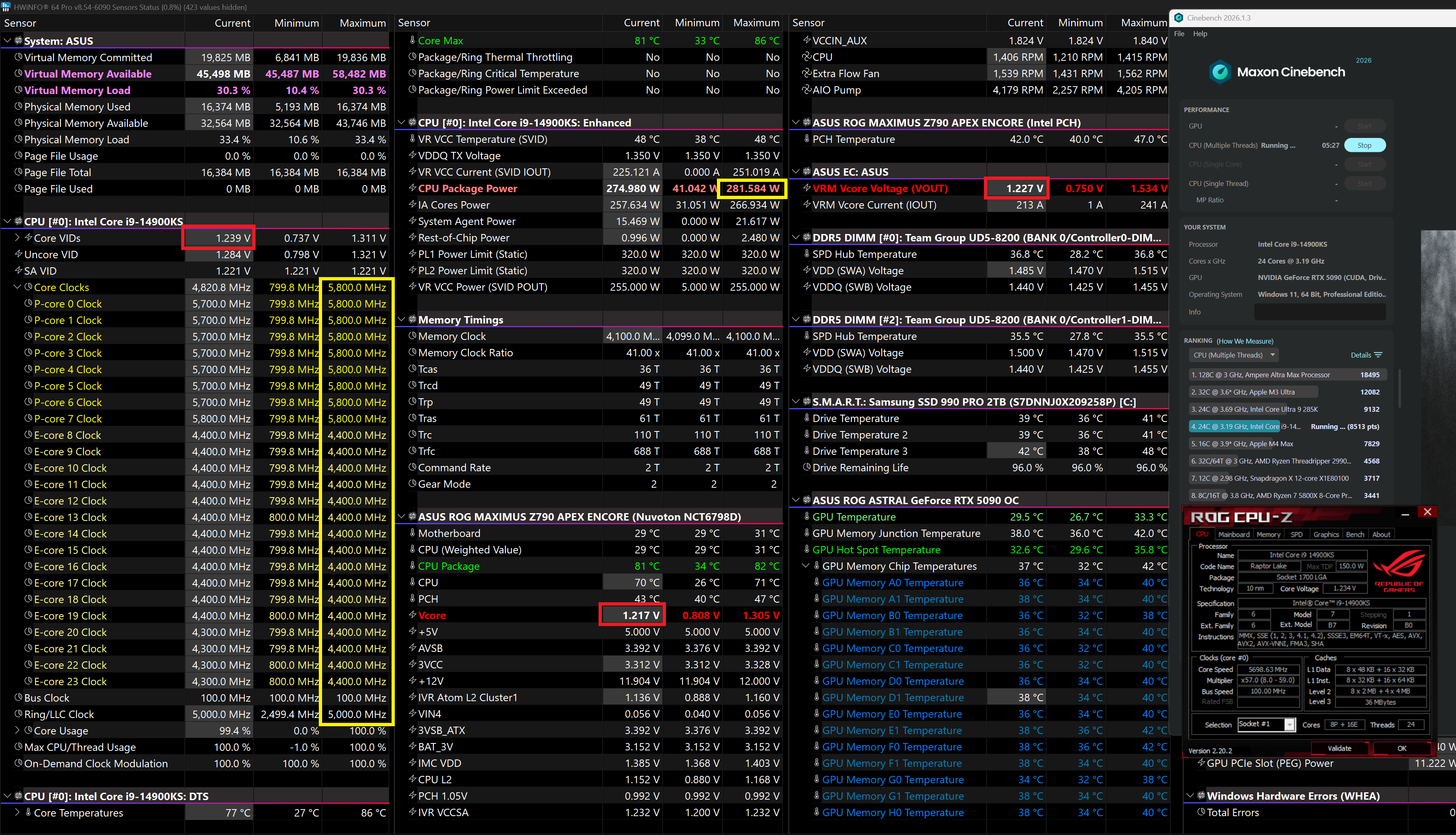
Test Cinebench, the y-cruncher component and the OCCT mode separately. Save an HWiNFO log; after warm-up, compare one interval without pauses or component changes. For fresh minima, reset Min/Max after the load settles.
Compare Vcore and VRM Vcore Voltage (VOUT)
On this system, my method expects Current and logged values to remain close throughout the cycle with small fluctuations. Exact equality is not required: sensing points, accuracy and polling differ. Two independent Minimum values do not describe one moment.
Check results and repeatability
Apply 5.3-5.4: errors/WHEA, temperatures, Effective Clocks, actual P/E/Ring, limits and results. Under limits, only attained clocks are validated. Compare small gains with baseline variation; matching voltages does not prove stability.
Must "SVID VMIN" match Vcore and VOUT?
No. Collapsed Core VIDs is an aggregate average of core VIDs, not the highest request or a direct command to the external VRM. Expand the group and read individual cores over the same interval. SVID is an interface; the CPU reports VID, while Vcore/VOUT are measurement channels.
The three rows may remain close throughout the cycle, but this is not required. Do not adjust DC to force VID = VOUT: the reading does not replace checks of the model, performance and stability.
9.3.2 Auto SVID: Monitoring Example
PDF · 27Page 27